Precision Motor Control with STM32 Peripherals: Advanced Timers, Position Sensors, and Dedicated Devices
Precision Motor Control with STM32 Peripherals: Advanced Timers, Position Sensors, and Dedicated Devices
Introduction
Driving a motor precisely is fundamentally a timing problem: the controller must place voltage transitions on a multi-phase bridge with tight phase relationships, insert dead time accurate to tens of nanoseconds to prevent shoot-through, and sample phase currents at a fixed point in the PWM cycle. A general-purpose timer that only generates a single PWM channel cannot do this. STM32 microcontrollers address the problem with a dedicated peripheral class — the advanced-control timer (TIM1 and TIM8) — engineered specifically for power-stage control, supported by general-purpose timers for position feedback and an analog subsystem for current sensing.
The practical relevance is that this peripheral set lets a single mainstream MCU run a full field-oriented control (FOC) loop without external logic, which is why STM32 dominates a large share of industrial and consumer motor drives. The engineering decisions that matter are: which timer topology matches the motor and control method, what shaft sensor (if any) is required, whether a dedicated motor-control part reduces the design, and how the timer clock determines the PWM duty-cycle resolution that ultimately bounds torque and speed smoothness.
The advanced-control timer as a power-stage engine
The defining feature of TIM1/TIM8 versus a general-purpose timer is the set of capabilities required to drive a half-bridge or full 3-phase bridge safely:
- Complementary outputs (CHx and CHxN): three channels produce six PWM signals, one pair per inverter leg, directly matching a 3-phase bridge.
- Hardware dead-time generator: a programmable delay between the turn-off of the high-side switch and turn-on of the low-side switch (and vice versa), set in timer-clock increments, preventing both switches conducting simultaneously.
- Center-aligned (up/down) counting: produces symmetric PWM, which lowers harmonic content and provides a natural mid-period instant for synchronized current sampling.
- Break inputs: an asynchronous hardware path that forces all outputs to a safe state on an over-current or fault signal, independent of software.
- Repetition counter and timer-triggered ADC: generates the control-loop interrupt at a programmable fraction of the PWM rate and triggers ADC conversion at a precise point in the cycle.
This combination is what allows the trapezoidal (six-step) or sinusoidal (FOC) modulation to be generated and the current measured deterministically. General-purpose timers (TIM2–TIM5, etc.) lack complementary outputs, dead time, and break inputs, so they are used for position feedback and auxiliary timing rather than the power stage.
Motor types and the matching scheme
| Motor type | Typical modulation | Core peripheral | Position sensor |
|---|---|---|---|
| Brushed DC | Single/dual PWM H-bridge | TIM with 1–2 channels | Optional (encoder/tacho) |
| BLDC | Six-step trapezoidal | TIM1/TIM8, 6 outputs | Hall sensors (or sensorless BEMF) |
| PMSM | Sinusoidal FOC | TIM1/TIM8 + ADC + math | Encoder/resolver (or sensorless) |
| Stepper | Microstepping PWM | TIM channels (current control) | Usually open-loop; encoder for closed-loop |
| AC induction | V/f or FOC | TIM1/TIM8 + ADC | Encoder for vector control |
Brushed DC needs only PWM and an H-bridge. BLDC at the simplest uses six-step commutation driven by Hall feedback. PMSM (and BLDC run as PMSM) uses FOC, which requires synchronized phase-current measurement and rotor angle, and is where the full advanced-timer-plus-ADC chain earns its place. Steppers are often open-loop but increasingly closed with an encoder to detect stall and reduce audible noise.
Position sensors and their STM32 interface
Whether a sensor is needed depends on the control method, not just the motor:
- Hall-effect sensors (BLDC six-step): three digital signals giving 60° commutation sectors. STM32 advanced timers include a dedicated Hall interface mode (XOR of three inputs into a timer channel via input capture) that timestamps commutation events and can trigger the next step automatically.
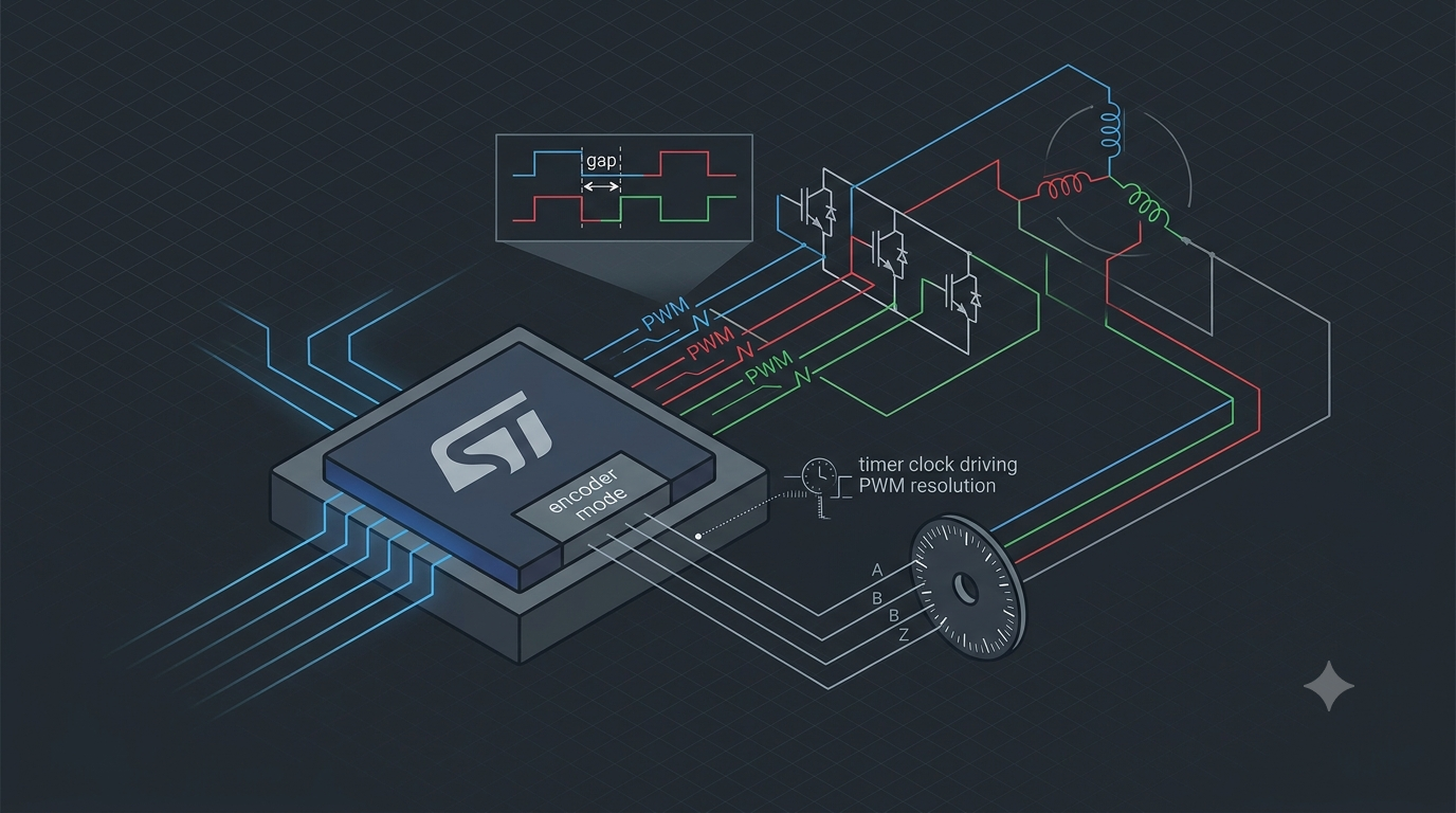
- Quadrature incremental encoders (PMSM/closed-loop): A/B channels decoded in hardware by a general-purpose timer configured in encoder mode, which counts edges up/down with direction and gives 4x resolution from the two channels; an index (Z) pulse provides a once-per-revolution reference.
- Absolute encoders (SPI/SSI/BiSS): deliver absolute angle without a homing move; interfaced over SPI or SSI rather than a timer. Used where the controller must know position at power-up.
- Resolvers: rugged analog sin/cos sensors common in automotive and harsh environments; require a resolver-to-digital conversion stage (external IC, or excitation via a timer/DAC with sin/cos sampled by the ADC).
- Sensorless: for PMSM/BLDC, rotor angle is estimated from back-EMF or current observers, removing the sensor entirely at the cost of poor low-speed/standstill behavior. This is the basis of the FOC firmware shipped for STM32 motor-control parts.
The selection rule: six-step BLDC pairs with Halls; precise FOC pairs with an incremental encoder (or resolver/absolute encoder where homing or robustness demands it); cost-sensitive designs go sensorless and accept the low-speed limitation.
Dedicated STM32 motor-control devices
Two STM32 families are specifically positioned for this domain. The STM32G4 series runs a Cortex-M4 with FPU at 170 MHz and includes 16-bit PWM timers dedicated to motor control, making it suitable for low-voltage, low-current BLDC and permanent-magnet motors; the B-G431B-ESC1 Discovery kit pairs an STM32G431 with a gate driver and MOSFETs to run sensorless FOC and six-step control out of the box.
The STSPIN32G4 integrates this further: it is a system-in-package combining an STM32G431 MCU, a triple half-bridge gate driver, and a power-management block in a 9x9 mm package, presented by ST as its first motor controller with an integrated MCU. It drives 3-phase brushless motors across a 5.5–75 V supply and can be programmed for sensorless or sensored FOC with one, two, or three shunts, more advanced position or torque control, or traditional six-step mode. It also embeds hardware protections including per-MOSFET VDS over-voltage monitoring and an interlock that prevents both switches in a leg being driven high simultaneously. The earlier STSPIN32F0 combines an STM32F0 core with Hall-decoding logic and a gate driver for simpler BLDC drives. Across both, the X-CUBE-MCSDK (Motor Control SDK) and its Workbench tool generate the PMSM/BLDC FOC firmware configuration, reducing the loop-tuning effort.
How timer clock frequency sets precision
The duty-cycle resolution of a PWM signal is set by how many timer-clock counts fit into one PWM period:
PWM_resolution_bits = log2( f_timer_clock / f_PWM )
At a 170 MHz timer clock and a 20 kHz PWM carrier, that is 170e6 / 20e3 = 8500 counts, roughly 13 bits of duty resolution. Halving the timer clock halves the count and removes one bit; doubling the PWM frequency does the same. Coarse duty resolution shows up directly as torque ripple and current-loop quantization, so the timer clock sets a hard ceiling on how smoothly the phase voltage can be commanded.
This ceiling is exactly what the high-resolution timer (HRTIM) on STM32G4 lifts. Rather than counting a physical clock, it uses a DLL to interpolate edge placement, achieving 184 ps resolution on frequency and duty cycle — equivalent to a 5.44 GHz timer clock — across 12 channels. The DLL operates with the APB2 clock between 100 and 170 MHz, yielding resolution scaling from 312 ps down to 184 ps. For comparison, the older STM32F334 HRTIM achieves 217 ps (10 channels) and the STM32H7 implementation 2.2 ns (12 channels). The same clock dependence also governs dead-time granularity (set in timer-clock steps), encoder maximum count rate, and the temporal precision of ADC trigger placement within the PWM cycle — all of which improve as the effective timer clock rises.
A compact HAL example: 3-phase complementary PWM with dead time
The advanced-timer configuration that matters most is the complementary 6-output setup with dead time and a break input. The following condensed HAL initialization shows the motor-control-specific fields; routine clock and GPIO setup is omitted.
TIM_HandleTypeDef htim1;

void MX_TIM1_MotorPWM_Init(void)
{
    htim1.Instance               = TIM1;                       // advanced-control timer
    htim1.Init.Prescaler         = 0;                          // full timer clock for max resolution
    htim1.Init.CounterMode       = TIM_COUNTERMODE_CENTERALIGNED1; // symmetric PWM
    htim1.Init.Period            = 8500 - 1;                   // 170MHz / 8500 ~= 20kHz carrier
    htim1.Init.RepetitionCounter = 1;                          // update event every full up/down cycle
    HAL_TIM_PWM_Init(&htim1);

    TIM_OC_InitTypeDef oc = {0};
    oc.OCMode      = TIM_OCMODE_PWM1;
    oc.Pulse       = 4250;                                     // 50% start point
    oc.OCPolarity  = TIM_OCPOLARITY_HIGH;
    oc.OCNPolarity = TIM_OCNPOLARITY_HIGH;                     // complementary output active level
    oc.OCIdleState = TIM_OCIDLESTATE_RESET;                    // safe state on break
    oc.OCNIdleState= TIM_OCNIDLESTATE_RESET;
    HAL_TIM_PWM_ConfigChannel(&htim1, &oc, TIM_CHANNEL_1);     // repeat for CH2, CH3 (phases V, W)

    TIM_BreakDeadTimeConfigTypeDef bd = {0};
    bd.DeadTime      = 85;        // ~0.5us dead time at 170MHz (85 / 170e6) - prevents shoot-through
    bd.BreakState    = TIM_BREAK_ENABLE;                       // hardware fault path
    bd.BreakPolarity = TIM_BREAKPOLARITY_LOW;
    bd.OffStateRunMode  = TIM_OSSR_ENABLE;
    bd.AutomaticOutput  = TIM_AUTOMATICOUTPUT_DISABLE;         // require explicit re-enable after fault
    HAL_TIMEx_ConfigBreakDeadTime(&htim1, &bd);

    // Start all three complementary pairs:
    HAL_TIM_PWM_Start(&htim1, TIM_CHANNEL_1);
    HAL_TIMEx_PWMN_Start(&htim1, TIM_CHANNEL_1);               // CH1N - low-side of phase U
    // ... CH2/CH2N, CH3/CH3N ...
}
The full FOC loop (Clarke/Park transforms, PI controllers, space-vector modulation, ADC-current sampling synchronized to the timer update event) is substantially larger and is best generated or adapted from the X-CUBE-MCSDK rather than hand-written, so it is not reproduced here.
Conclusion
Precision motor control on STM32 rests on the advanced-control timer (TIM1/TIM8), whose complementary outputs, hardware dead-time generation, break inputs, and timer-synchronized ADC triggering provide everything a 3-phase power stage needs in one peripheral. General-purpose timers in encoder mode and the integrated analog chain close the position and current loops, and the timer clock frequency directly sets the duty-cycle resolution — with the HRTIM on STM32G4 pushing effective resolution to 184 ps where the application demands it.
Use a basic timer with one or two PWM channels for brushed DC. Use TIM1/TIM8 with Hall feedback for cost-driven six-step BLDC. Move to the full advanced-timer-plus-ADC chain with an incremental encoder (or resolver/absolute encoder) for FOC on PMSM where smooth torque and accurate positioning are required, and adopt sensorless estimation only where the low-speed and standstill limitations are acceptable. For integrated designs, the STM32G4 and the STSPIN32G4 system-in-package collapse MCU, gate driver, and protection into a small footprint with mature FOC firmware support. Conversely, a dedicated motor-control part is unnecessary for low-dynamic open-loop drives, where the added analog and high-resolution timing capability would go unused.
References / Further Reading
- STMicroelectronics. (2024). RM0440: STM32G4 Series Advanced Arm-based 32-bit MCUs — Reference Manual. STMicroelectronics.
- STMicroelectronics. STSPIN32G4 — Integrated 3-phase BLDC motor controller with STM32G431 MCU, Datasheet. st.com.
- STMicroelectronics. STM32G4 HRTIM product training and cross-series timer overview. st.com.
- STMicroelectronics. X-CUBE-MCSDK — STM32 Motor Control Software Development Kit and Motor Control Workbench, User Manual. st.com.
- STMicroelectronics. B-G431B-ESC1 Discovery kit — Electronic speed controller, User Manual. st.com.
