EMC-Aware Firmware: How Software Decisions Affect Radiated Emissions and ESD Robustness
Introduction
When a product fails a CISPR radiated-emissions scan or an IEC 61000-4-2 ESD test, the response is almost always hardware-centric: add ferrites, reroute a clock trace, fit larger transient-voltage-suppression (TVS) diodes, improve the ground stitching. These are valid and frequently necessary. What gets ignored is that the firmware running on the device is continuously programming the physics — it sets GPIO slew rates, chooses clock frequencies, decides when a DC-DC converter dithers, and determines whether a corrupted configuration register stays corrupted for milliseconds or microseconds.
A firmware change costs nothing per unit and ships as an update; a hardware respin costs a layout cycle, tooling, and weeks of schedule. Treating EMC as partly a software problem therefore has an outsized return. The two domains examined here are distinct: radiated emissions concern what the device transmits, while ESD robustness concerns how the device behaves under transient assault. Firmware has meaningful leverage over both.
The Coupling Between Software and the RF Spectrum
Radiated emissions are dominated by high-frequency harmonic content, and that content is produced by fast voltage and current transitions. Several of the variables that determine those transitions are register-configurable and therefore owned by firmware.
Edge rates and GPIO drive strength
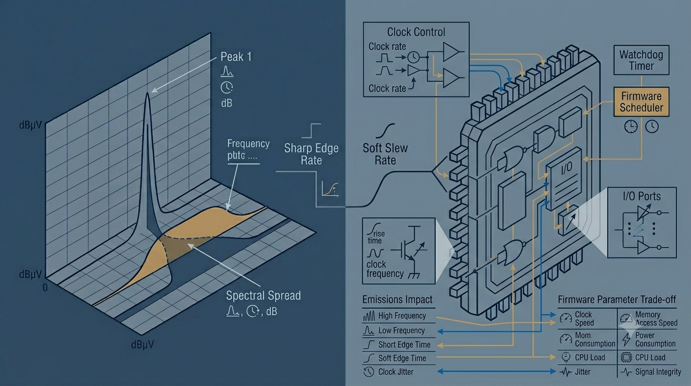
The harmonic envelope of a digital signal rolls off based on its rise/fall time, not just its fundamental frequency. A signal with a 2 ns edge carries significant energy well past 150 MHz; the same logical signal with a 20 ns edge concentrates its energy an order of magnitude lower. Most MCUs expose per-pin slew-rate or output-speed control, and the default after reset is rarely the quietest option.
// STM32-style: force a non-critical output (status LED, slow strobe) to the
// lowest slew rate. Lower dV/dt => weaker high-order harmonics radiated.
GPIOB->OSPEEDR &= ~(3U << (2 * LED_PIN));   // clear the 2-bit speed field
GPIOB->OSPEEDR |=  (0U << (2 * LED_PIN));   // 0b00 = low speed (~2 MHz class)
// Reserve high drive strength only for pins with real timing needs,
// e.g. a high-rate SPI clock or an external memory bus.
The discipline here is auditing every configured pin and asking whether it actually needs a fast edge. Reset defaults and copy-paste init code routinely leave low-bandwidth signals running at maximum slew.
Clock architecture and spread-spectrum
Clocks and their integer harmonics are the sharpest peaks on any emissions plot, because a fixed-frequency clock dumps all of its energy into discrete spectral lines. A quasi-peak detector (as specified in CISPR 16 measurement methodology) rewards exactly this kind of narrowband concentration. Spread-spectrum clocking (SSC) modulates the clock frequency by a small percentage so that the energy of each line is smeared across a band, lowering the measured peak by several dB without changing the total emitted power.
SSC is frequently a PLL configuration bit. Enabling it is a firmware decision, as is choosing the modulation depth and profile:
// Enable down-spread modulation on the main PLL (concept; field names vary).
// Trades a small frequency error for a multi-dB reduction in peak emissions.
RCC->SSCGR  = (MOD_PERIOD << 0)        // modulation period
            | (INC_STEP   << 13);      // step => spread depth (~0.5-2%)
RCC->SSCGR |= RCC_SSCGR_SSCGEN;        // enable; must be set before PLL lock
Beyond SSC, firmware controls which PLL ratios are active, whether unused peripheral clocks are gated off (silent peripherals do not radiate), and whether the core uses dynamic voltage and frequency scaling (DVFS) to drop to the lowest frequency that still meets deadlines.
Switching synchronization and activity scheduling
When multiple subsystems switch at the same rate and phase, their harmonics add coherently and the emission peaks grow. Firmware can deliberately decorrelate them. Two common techniques:
- Phase-shifting PWM channels so that motor or LED drivers do not all transition on the same edge, spreading the current draw and its associated radiated field.
- Dithering or jittering periodic activity — polling intervals, sensor reads, radio wake-ups — so repetitive bursts do not form a clean comb in the spectrum.
// Dither a PWM carrier to spread energy around f_pwm instead of stacking it
// onto a single line. Compensate duty so the average output is unchanged.
int8_t   d        = (int8_t)(prng() & 0x07) - 3;   // +/-3 ticks of jitter
uint16_t arr      = BASE_ARR + d;
TIM1->ARR  = arr;
TIM1->CCR1 = (uint16_t)((uint32_t)BASE_CCR * arr / BASE_ARR); // keep duty
A summary of the principal firmware levers:
| Firmware lever | Emission mechanism affected | Typical benefit | Cost / caveat |
|---|---|---|---|
| Lower GPIO slew rate | High-order harmonics from fast edges | Several dB on upper bands | Limits max usable data rate |
| Enable spread-spectrum clock | Narrowband clock peaks | 3–10 dB peak reduction | Adds jitter; harmful to clock recovery / audio |
| Gate unused peripheral clocks | Active circuit count | Removes whole harmonic families | Re-enable latency on wake |
| Phase-shift PWM channels | Coherent harmonic addition | Lower peak current bursts | Slightly more complex timer setup |
| Dither periodic tasks | Comb of activity harmonics | Spectral smearing | Less deterministic timing |
ESD: From Hardware Clamps to System-Level Resilience
ESD immunity (tested per IEC 61000-4-2, with contact and air-discharge levels up to ±8 kV and beyond) starts with hardware: clamps, current-return paths, and creepage. But hardware protection is rated to survive a discharge, not to guarantee that software keeps running correctly through it. A discharge that does not destroy silicon can still inject enough energy to flip a configuration bit, corrupt an in-flight bus transaction, or push a state machine into an unintended state. Firmware determines whether that disturbance is a momentary glitch or a permanent hang.
Failure modes ESD induces in a running system
- Silent register corruption — a flipped bit in a GPIO direction, clock, or interrupt-enable register with no accompanying CPU reset.
- Corrupted transactions — a UART byte, SPI word, or I²C transfer mangled mid-flight, including slaves left holding a bus line low.
- State-machine derailment — a program counter or RAM variable disturbed into a state with no defined exit.
- Spurious inputs — injected edges on GPIO or ADC lines read as legitimate events.
Defensive firmware techniques
The core idea is assume corruption will occur and design for fast, deterministic recovery. Several patterns:
Configuration integrity checking. Keep a canonical shadow of critical configuration and periodically verify the live registers against it.
// Detect silent corruption of GPIO config and restore the known-good state.
void config_integrity_task(void) {
    if (GPIOA->MODER != gpioa_moder_shadow) {  // compare to canonical value
        reinit_gpioa();                        // restore from authoritative config
        fault_log(EVT_REG_CORRUPTION);         // record for field diagnostics
    }
}
Windowed watchdog plus reset-cause analysis. A window watchdog (WWDG) catches code that has stalled or run away (refreshing too early), which a simple independent watchdog (IWDG) cannot. On reboot, classify the reset source and drive recovery policy from it.
uint32_t csr = RCC->CSR;
if (csr & RCC_CSR_WWDGRSTF) {   // last reset came from the window watchdog
    enter_safe_state();          // degraded but controlled operation
    persist_fault_counter();     // escalate if it keeps happening
}
RCC->CSR |= RCC_CSR_RMVF;        // clear reset flags for next cycle
Bus recovery. I²C in particular leaves a slave holding SDA low after a glitch. The defined recovery is to manually clock SCL until the slave releases, then issue STOP.
for (int i = 0; i < 9 && sda_is_low(); i++) {  // up to 9 clocks flushes a byte
    scl_low();  delay_us(5);
    scl_high(); delay_us(5);
}
generate_stop_condition();                     // return the bus to idle
Defensive state machines and data redundancy. Every state machine needs an explicit default branch that recovers to a safe state rather than continuing from an undefined one. Critical variables can be stored redundantly (e.g., a value and its bitwise complement, or a CRC over a config block) and validated before use. Inputs should be debounced and range-checked so an injected edge is rejected as implausible.
| ESD-induced failure | Firmware mitigation |
|---|---|
| Silent register corruption | Periodic config verification against shadow copy |
| CPU hang / runaway | Windowed watchdog + reset-cause-driven recovery |
| Stuck I²C bus | Manual SCL clocking + STOP recovery sequence |
| Corrupted transfer | CRC, sequence numbers, timeout-and-retry |
| Spurious input edge | Debounce + plausibility/range checks |
| State-machine derail | Explicit default branch to safe state |
Conclusion
Firmware is a genuine EMC design surface, not a bystander. On the emissions side, the strongest levers are slowing edges on signals that do not need to be fast, enabling spread-spectrum clocking, gating idle clocks, and decorrelating switching activity — each capable of moving a compliance scan by several dB at near-zero unit cost. On the immunity side, robustness comes from assuming corruption will happen and engineering for fast, deterministic recovery: integrity checks on critical registers, windowed watchdogs with reset-cause logic, bus-recovery routines, redundant data, and defensive state machines.
These techniques are appropriate when you want margin without a hardware respin, when the product ships firmware updates, or when system-level immunity (recovery behavior) matters as much as component survival. They are not substitutes for sound hardware: spread-spectrum clocking will not rescue a board with a poor ground return, and a watchdog cannot protect silicon that an unclamped discharge physically destroys. The right posture is co-design — firmware levers buy margin and resilience on top of competent hardware, and the cheapest dB and the fastest recovery path are often found in code that already exists.
