DMA Controllers: Reducing CPU Load in High-Throughput Embedded Systems
Introduction
In any system where a peripheral produces or consumes data faster than the CPU can comfortably service per-word interrupts, the limiting factor stops being clock frequency and becomes data-movement overhead. A Cortex-M running an interrupt service routine (ISR) per received byte on a 10 Mbit UART link is already spending a non-trivial fraction of its cycles on context save/restore. Scale that to a MIPI CSI-2 camera, a gigabit Ethernet MAC, or an OctoSPI flash streaming at several hundred MB/s, and a per-transfer CPU model collapses entirely.
The Direct Memory Access (DMA) controller exists precisely to break this coupling: it moves blocks of data between memory and peripherals — or memory and memory — autonomously, signaling the CPU only at meaningful boundaries (block complete, half-transfer, error). What has changed in recent silicon is not the basic idea but the sophistication of the engines themselves. Modern DMA controllers are programmable, descriptor-driven, security-aware data-movement processors, and treating them as "fire-and-forget copy blocks" leaves significant performance and integration value unused.
DMA Fundamentals
At minimum, a DMA transfer is defined by a source address, a destination address, a transfer size, and an address-progression rule for each endpoint (increment, fixed, or modulo/wrap). The controller arbitrates for the system bus, performs the transfer, and raises an interrupt on completion.
The two classical arbitration strategies remain relevant:
- Cycle stealing — the DMA takes the bus for individual beats, interleaving with CPU accesses. Lower peak throughput, lower CPU stall.
- Burst mode — the DMA holds the bus for a full burst (e.g., an AXI INCR burst of 16 beats). Higher throughput, but the CPU may stall waiting for the bus.
Real controllers expose a configurable burst length and an internal FIFO so that a slow peripheral side and a fast memory side can be rate-matched without bus thrash.
Transfers are triggered either by software or — far more commonly in embedded work — by a hardware request line asserted by a peripheral (UART RX-not-empty, ADC end-of-conversion, timer update, SPI TX-empty). This hardware-paced model is what makes truly zero-CPU streaming possible.
Why CPU offload is not "free"
Two costs survive even a perfect DMA setup, and ignoring them produces designs that benchmark worse than expected:
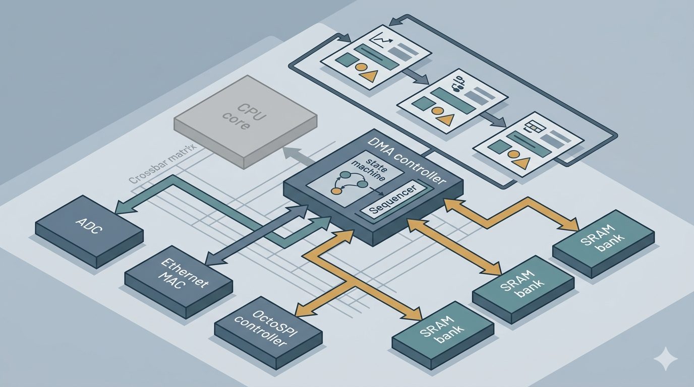
- Bus contention. DMA and CPU share the interconnect and memory. On a single-bank SRAM, a saturating DMA channel will stall the CPU on every cache miss. Multi-bank SRAM and a multi-layer AXI/AHB matrix exist specifically to let DMA and CPU hit different memories concurrently.
- Cache coherency. On a Cortex-M7 or a Cortex-A core with L1 data cache, a DMA write to a buffer is invisible to the CPU until the line is invalidated; a CPU write may sit in cache and never reach the buffer the DMA reads. This must be handled by cache maintenance or by placing buffers in a non-cacheable MPU region.
/* Receive path on a cached core (e.g. Cortex-M7).
 * Buffer is in cacheable memory, so the cache must be told
 * the DMA wrote underneath it before the CPU reads. */
SCB_InvalidateDCache_by_Addr((uint32_t*)rx_buf, RX_LEN);  // discard stale lines
process(rx_buf, RX_LEN);                                   // now CPU sees DMA data

/* Transmit path: flush CPU-written data to memory
 * before starting the DMA that reads it. */
SCB_CleanDCache_by_Addr((uint32_t*)tx_buf, TX_LEN);        // push dirty lines out
dma_start(tx_buf, TX_LEN);
Modern DMA Controller Architectures
Three controller families illustrate the spread of current designs.
| Controller | Programming model | Notable features |
|---|---|---|
| ARM PL330 (AMBA AXI) | Executes a small DMA instruction set (microcode) | DMALD/DMAST/DMALP loops; multiple independent threads; common in Cortex-A SoCs |
| NXP eDMA (e.g. i.MX RT) | Transfer Control Descriptor (TCD) per channel | Nested minor/major loops; channel linking; scatter-gather via in-memory TCDs |
| STMicro GPDMA (STM32U5/H5/H7) | Linked-list of descriptors in memory | 2D addressing, request multiplexing, per-channel security/privilege attributes |
The architectural trend is clear: the controller is increasingly a descriptor-driven state machine that reads its own work items from memory, rather than a set of registers the CPU rewrites for every transfer.
Linked-list / scatter-gather descriptors
The single most important modern feature is the ability to chain transfers. Instead of one contiguous copy, the controller follows a linked list of descriptors, each describing its own source, destination, length, and a pointer to the next descriptor. This enables:
- Gather of fragmented buffers (typical for network packets assembled from headers + payload pools) into a single stream.
- Scatter of an incoming stream into multiple discontiguous regions.
- Continuous operation with the CPU touching only the descriptor list, not the data path.
/* GPDMA-style linked-list node. The engine fetches one node,
 * executes the block transfer, then follows next_node.
 * The CPU builds the list once; the data path runs unattended. */
typedef struct dma_lli {
    uint32_t src;            // peripheral or memory source address
    uint32_t dst;            // destination address
    uint32_t nbytes;         // block size for this node
    struct dma_lli *next;    // NULL terminates the list (or wraps for ring)
} dma_lli_t;

dma_lli_t rx_chain[3] = {
    { ADC_DR, (uint32_t)buf_a, 1024, &rx_chain[1] },
    { ADC_DR, (uint32_t)buf_b, 1024, &rx_chain[2] },
    { ADC_DR, (uint32_t)buf_c, 1024, &rx_chain[0] }, // wrap -> triple-buffer ring
};
The wrapped list above gives a triple-buffer ring with zero CPU involvement per buffer: the controller advances through buf_a -> buf_b -> buf_c -> buf_a, raising an interrupt at each node boundary so application code can consume the just-filled buffer while the next fills.
2D / strided addressing
Newer controllers (STM32 GPDMA, eDMA via minor/major loop offsets) support a second address dimension: after transferring a block, the source and/or destination address jumps by a programmable offset. This is exactly what is needed to:
- Extract a rectangular region of interest from a larger frame buffer (line stride != region width).
- De-interleave multi-channel ADC samples into separate per-channel arrays.
- Repack pixel formats during transfer.
What previously required a CPU loop with pointer arithmetic now executes entirely in the DMA engine.
Request multiplexing (DMAMUX)
Older parts hard-wired each peripheral to a fixed DMA channel, producing painful resource conflicts. The request multiplexer (DMAMUX, now standard across STM32 and many other vendors) inserts a crossbar between peripheral request lines and DMA channels, so any request can drive any channel. It also adds:
- Request generators — convert an external trigger or timer event into a DMA request.
- Synchronization — gate requests on an external signal, useful for sample-accurate acquisition.
Security and isolation
With TrustZone reaching microcontroller-class parts, DMA became an attack surface: a peripheral-driven engine with bus-master access can read or write anywhere unless constrained. Modern controllers attach security and privilege attributes per channel, so a non-secure context cannot program a channel to touch secure memory. In safety- and security-critical designs this is no longer optional.
Matching modern peripheral throughput
The features above exist because peripheral bandwidth has outrun per-interrupt servicing:
- Gigabit Ethernet / USB 3.x / SDMMC ship with their own dedicated, descriptor-based DMA in the MAC/controller — the general-purpose DMA is bypassed entirely for the data path.
- OctoSPI / HyperBus flash at hundreds of MB/s rely on burst-mode DMA with deep FIFOs to keep the external bus saturated.
- High-speed ADCs and audio (I2S/SAI) depend on circular/linked-list DMA for glitch-free continuous capture.
At these rates the bottleneck moves off the CPU and onto memory bandwidth and interconnect arbitration — which is why the modern question is less "does it have DMA?" and more "how many independent bus masters and memory banks can run concurrently?"
Conclusion
DMA has shifted from a peripheral convenience to a central architectural lever for throughput-bound embedded systems. The practical takeaways:
- Use hardware-triggered DMA for any peripheral that streams faster than a comfortable interrupt rate; reserve the CPU for boundary events only.
- Reach for linked-list / scatter-gather descriptors and ring buffers to eliminate per-buffer CPU intervention in continuous acquisition.
- Exploit 2D addressing to push pointer arithmetic (strides, ROI extraction, de-interleaving) into the engine.
- Always budget for cache maintenance and bus contention — these are the costs that erode the theoretical CPU savings, and on multi-bank/multi-layer designs they are addressable.
DMA is not the right tool everywhere. For small, infrequent transfers, descriptor setup and cache maintenance can cost more cycles than a simple memcpy. For tight, deterministic control loops where worst-case latency matters more than throughput, the added bus contention and completion-interrupt latency may be undesirable. The discipline is to apply DMA where data volume is high and per-transfer CPU attention is the bottleneck — and to leave it out where transfer sizes are small or determinism dominates.