Clock Domain Crossing (CDC) Failure Modes and Verification: Synchronizers, Handshakes, and Asynchronous FIFOs
Clock Domain Crossing (CDC) Failure Modes and Verification: Synchronizers, Handshakes, and Asynchronous FIFOs
Introduction
Any non-trivial SoC or FPGA design integrates blocks running on independent clocks: a CPU subsystem, a high-speed transceiver recovered clock, an external ADC clock, a peripheral bus, a memory controller. Wherever a signal generated by one clock is sampled by an unrelated clock, the receiving register can be clocked while its data input is changing. The result is a setup or hold timing violation that static timing analysis (STA) cannot constrain away, because there is no fixed phase relationship between the two clocks to constrain.
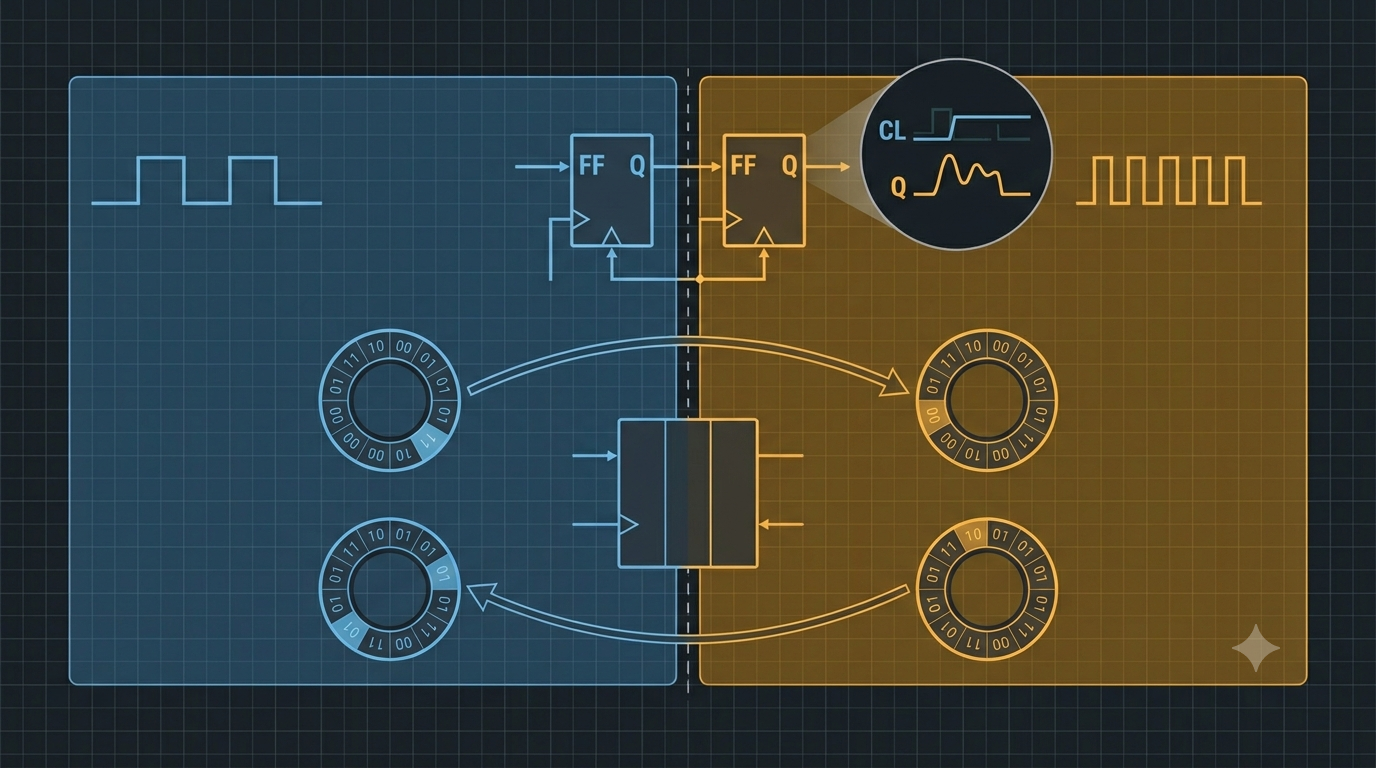
The practical consequence is metastability: the register output may hover at an intermediate voltage for an unbounded (though probabilistically short) time before resolving to a logic 0 or 1. A single unsynchronized crossing in a control path can produce intermittent, low-frequency failures that pass every functional simulation, survive bench bring-up, and surface as field returns. Because the effect is statistical and timing-dependent, CDC is one of the few problem classes that mainstream RTL simulation is structurally incapable of catching. This makes disciplined design patterns and dedicated CDC verification mandatory rather than optional.
The physical problem: metastability
A flip-flop guarantees a defined output only if its data input is stable across the setup and hold window around the active clock edge. When the source and destination clocks are asynchronous, this window is eventually violated. The flop can enter a metastable state and take an additional resolution time to settle. The reliability of a single sampling stage is characterized by mean time between failures:
MTBF = exp(t_r / tau) / (T0 * f_clk * f_data)
where t_r is the resolution time available before the next stage samples, tau and T0 are technology-dependent constants of the flop, f_clk is the destination sampling frequency, and f_data is the toggle rate of the incoming signal. The dominant term is the exponential: every extra unit of t_r improves MTBF by orders of magnitude. This is exactly what a synchronizer buys — it allocates one or more full destination clock periods purely for metastability resolution.
Two facts follow directly and drive every technique below:
- A synchronizer reduces the probability of metastable propagation; it never eliminates the source flop entering metastability. The goal is an MTBF measured in years, not zero events.
- Resolution outcome is independent per bit. A multi-bit bus sampled by independent synchronizers can resolve to a mix of old and new values on the same edge, producing a value that never existed in the source domain (data incoherence).
Two-flop synchronizer (single-bit control)
The two-flop (double-flop) synchronizer is the baseline primitive for crossing a single, slowly changing control or status bit. The first flop absorbs the violation and is given one full destination period to resolve before the second flop samples it.
Verilog:
module sync_2ff #(
    parameter WIDTH = 1          // MUST stay 1 for unrelated bits; never widen for a bus
) (
    input  wire             dclk,     // destination clock
    input  wire             drst_n,   // destination async reset, active low
    input  wire [WIDTH-1:0] async_in, // bit(s) from source domain
    output reg  [WIDTH-1:0] sync_out  // safe in destination domain
);
    (* ASYNC_REG = "TRUE" *) reg [WIDTH-1:0] meta;  // tool hint: pack flops together, no opt

    always @(posedge dclk or negedge drst_n) begin
        if (!drst_n) begin
            meta     <= {WIDTH{1'b0}};
            sync_out <= {WIDTH{1'b0}};
        end else begin
            meta     <= async_in;  // capture stage: setup/hold may be violated here
            sync_out <= meta;      // one full dclk period reserved for resolution
        end
    end
endmodule
VHDL:
library ieee;
use ieee.std_logic_1164.all;

entity sync_2ff is
  generic ( WIDTH : positive := 1 );          -- single control bit only
  port (
    dclk     : in  std_logic;                 -- destination clock
    drst_n   : in  std_logic;                 -- async reset, active low
    async_in : in  std_logic_vector(WIDTH-1 downto 0);
    sync_out : out std_logic_vector(WIDTH-1 downto 0)
  );
end entity;

architecture rtl of sync_2ff is
  signal meta : std_logic_vector(WIDTH-1 downto 0);
  signal sync : std_logic_vector(WIDTH-1 downto 0);
  attribute async_reg : string;               -- keep both stages adjacent, no retiming
  attribute async_reg of meta : signal is "TRUE";
  attribute async_reg of sync : signal is "TRUE";
begin
  process (dclk, drst_n)
  begin
    if drst_n = '0' then
      meta <= (others => '0');
      sync <= (others => '0');
    elsif rising_edge(dclk) then
      meta <= async_in;                       -- may be metastable
      sync <= meta;                           -- resolved after one period
    end if;
  end process;
  sync_out <= sync;
end architecture;
Validity conditions and limits: the two-flop synchronizer is only valid for a single bit. It does not guarantee that a source pulse narrower than one destination period will be captured (pulse loss), and it must never be instantiated per-bit across a bus, because the bits resolve independently. For an event-style pulse crossing into a faster or slower domain, use a toggle (level-flip) synchronizer: the source toggles a level on each event, the level is two-flop synchronized, and an edge detector in the destination regenerates the pulse.
Handshake (multi-bit, low rate)
When multiple bits must cross coherently but throughput is low — configuration words, status snapshots — a request/acknowledge handshake transfers the data while only the control flags cross the domain boundary through synchronizers. The bus itself is held stable by the source until the destination has captured it, so the bus bits are never sampled while changing.
Source domain:                          Destination domain:
  1. drive data_bus, assert req           a. req crosses via 2-FF synchronizer
  2. wait for ack (synchronized back)     b. on synchronized req: latch data_bus
  3. deassert req                            (bus is stable -> no CDC on data)
  4. wait for ack deassert (4-phase)      c. assert ack; ack crosses back via 2-FF
A four-phase handshake costs several clock periods per transfer in each direction, so it is throughput-limited. Its strength is that the data path carries no synchronizer and stays coherent by construction. The MUX-recirculation variant (data + load-enable) is a lighter alternative where the source guarantees data stability for the full synchronization latency.
Asynchronous FIFO (multi-bit, high throughput)
For continuous, high-bandwidth streams the standard solution is a dual-clock FIFO built on a dual-port RAM, with read and write pointers that each cross into the opposite domain to compute the full and empty flags. The critical CDC insight is that the pointers are Gray-coded before crossing: a Gray counter changes exactly one bit per increment, so even if that bit resolves to the old or new value, the synchronized pointer is only ever the correct current or correct previous count — never a corrupt intermediate.
// Gray pointer generation and cross-domain sync (core CDC element of an async FIFO)
module gray_ptr #(parameter ADDR = 4) (
    input  wire            clk, rst_n, inc,   // local domain
    output reg  [ADDR:0]   ptr_gray,          // this domain's Gray pointer
    output wire [ADDR-1:0] addr               // RAM address (binary, local use only)
);
    reg  [ADDR:0] bin;
    wire [ADDR:0] bin_next  = bin + inc;                  // gate inc with full/empty externally
    wire [ADDR:0] gray_next = (bin_next >> 1) ^ bin_next; // binary -> Gray: one bit changes

    always @(posedge clk or negedge rst_n)
        if (!rst_n) begin bin <= 0; ptr_gray <= 0; end
        else        begin bin <= bin_next; ptr_gray <= gray_next; end

    assign addr = bin[ADDR-1:0];               // MSB is the wrap bit, not addressed
endmodule
Each pointer is registered in Gray form, then synchronized into the other domain through a two-flop synchronizer over the whole Gray word (legal here precisely because only one bit can differ at a time). Empty is asserted when the read Gray pointer equals the synchronized write Gray pointer; full is asserted when the write Gray pointer equals the synchronized read Gray pointer with the two MSBs inverted. A correct, complete reference implementation is Cummings' SNUG style-1/style-2 FIFO; the snippet above isolates the part that actually crosses domains.
Technique comparison
| Technique | Signal type | Coherent multi-bit | Throughput | Latency | Complexity |
|---|---|---|---|---|---|
| Two-flop synchronizer | Single control/status bit | No | n/a (level) | ~2 dest cycles | Trivial |
| Toggle/pulse synchronizer | Single event/pulse | No | Limited by 2-FF | ~2-3 cycles | Low |
| Handshake (req/ack) | Multi-bit, low rate | Yes | Low | Several cycles/word | Moderate |
| Async FIFO (Gray ptrs) | Multi-bit stream | Yes | High | Buffer + a few cycles | High |
Why functional simulation hides the bug
Event-driven RTL simulation evaluates registers with zero or unit delay and forces every flop to a defined 0 or 1 on each edge. There is no metastable state in the model, no resolution time, and no probability of capturing old-versus-new data. Consequently:
- A missing or incorrect synchronizer simulates cleanly, because the simulator silently picks a deterministic value where silicon would occasionally resolve the other way.
- Data incoherence on an unsynchronized bus does not appear, because all bits update atomically in the model.
- Even gate-level simulation with SDF back-annotation reports a setup/hold violation but still resolves the flop to a fixed value; it does not reproduce the statistical resolution behavior.
CDC closure therefore depends on tooling outside ordinary simulation:
- Structural CDC analysis (lint): SpyGlass CDC, Questa CDC, VC SpyGlass — identify every crossing and verify a recognized synchronizer is present and correctly structured.
- Metastability injection: the CDC tool injects randomized delay/inversion on resolved synchronizer outputs and re-runs functional sim, exposing logic that assumes a particular resolution.
- Formal protocol checks: prove handshake and Gray-pointer properties hold under all relative clock phases.
- Reset-domain-crossing (RDC) analysis: the same metastability mechanism applies to asynchronous resets and is checked separately.
Design rules summary
- Synchronize every crossing exactly once; converging multiple synchronized copies of the same signal into combinational logic reintroduces incoherence.
- Use a two-flop synchronizer only for a single bit; never instantiate it per-bit across a bus.
- Transfer multi-bit values by handshake (low rate) or async FIFO (streaming) so the data bus is never sampled while changing.
- Gray-code any multi-bit counter that must cross a domain; synchronize the Gray word, convert back to binary only in the local domain.
- Apply
ASYNC_REG/async_reg(or the vendor equivalent) and keep synchronizer flops physically packed; block retiming, optimization, and equivalent-register merging on them. - Add explicit timing exceptions (
set_false_pathorset_max_delay -datapath_only) on the first synchronizer stage so STA does not attempt to constrain an unconstrainable path. - Size the resolution budget for the required MTBF: add a third flop or insert a slower intermediate clock for very high source toggle rates.
- Do not rely on functional simulation for CDC sign-off; run structural CDC analysis plus metastability injection, and treat RDC as a first-class check.
Conclusion
Clock domain crossing failures originate in a physical effect — flip-flop metastability — that conventional STA cannot constrain and conventional RTL simulation cannot observe. The mitigation is a small set of well-understood structures matched to the signal type: a two-flop synchronizer for single control bits, a request/acknowledge handshake for coherent low-rate multi-bit transfers, and a Gray-pointer asynchronous FIFO for high-throughput streams. Each works by reserving destination clock periods for metastability resolution and, for multi-bit cases, by ensuring the data path is never sampled mid-transition.
Use a two-flop synchronizer when the crossing is a single, slowly changing level. Use a handshake when several bits must cross together but bandwidth is low and latency is acceptable. Use an async FIFO when the design needs sustained throughput across the boundary and can absorb the LUT/RAM cost. Avoid ad-hoc per-bit synchronizers on buses, avoid relying on pulse width assumptions for event signals, and never treat a clean functional simulation as CDC sign-off — that is precisely the case the simulator cannot model. Pair the structural patterns above with dedicated CDC and RDC analysis to convert an unbounded statistical risk into a quantified, accepted MTBF.
References / Further Reading
- Cummings, C. E. (2008). Clock Domain Crossing (CDC) Design & Verification Techniques Using SystemVerilog. SNUG Boston.
- Cummings, C. E. (2002). Simulation and Synthesis Techniques for Asynchronous FIFO Design. SNUG San Jose.
- Ginosar, R. (2011). Metastability and Synchronizers: A Tutorial. IEEE Design & Test of Computers, 28(5), 23-35.
- Verma, S., & Dabare, A. S. (2007). Understanding Clock Domain Crossing Issues. EE Times / synchronization design notes.
